Dashboard overview
 images/active-source/generator.png
images/active-source/inverting.png
images/active-source/generator.png
images/active-source/inverting.png
Read input configuration from:
N/{portalId}/settings/0/Settings/SystemSetup/AcInput1
N/{portalId}/settings/0/Settings/SystemSetup/AcInput2
// 0: not in use; 1: grid, 2: generator, 3: shore
Read active source from:
N/{portalId}/vebus/{vebusInstanceId}/Ac/ActiveIn/ActiveInput
//  0 = ACin-1, 1 = ACin-2, 240 is none (inverting).
Based on which ACin is active, show the title: "Shore Power" / "Generator" / "Inverting".
[ ] Check - what do we want to show when inverting?
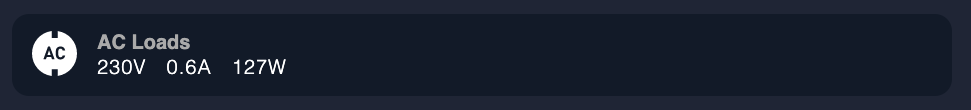
Read the voltage from:
N/{portalId}/vebus/{deviceInstanceId}/Ac/ActiveIn/L1/V
Sum the current of the three phases:
N/{portalId}/vebus/{deviceInstanceId}/Ac/ActiveIn/L1/I
N/{portalId}/vebus/{deviceInstanceId}/Ac/ActiveIn/L2/I
N/{portalId}/vebus/{deviceInstanceId}/Ac/ActiveIn/L3/I
Sum the power of the three phases:
N/{portalId}/vebus/{deviceInstanceId}/Ac/ActiveIn/L1/P
N/{portalId}/vebus/{deviceInstanceId}/Ac/ActiveIn/L2/P
N/{portalId}/vebus/{deviceInstanceId}/Ac/ActiveIn/L3/P
The user can see the currently selected limit. When clicking the button, a popup appears with values suggested for changing the amperage.
Note: Paths for /CurrentLimit described below are only available starting from version 415 of the VE.Bus device.
images/shore-power-limit/shore-power-limit.png
First, determine which one of the inputs is configured to shore power as described above (ACin-1 or ACin-2). Then, based on that, read the value of:
N/{portalId}/vebus/{vebusInstanceId}/Ac/In/{inputId}/CurrentLimit
images/shore-power-limit/power-limit-suggestions.png
The list of amperages displayed depends on whether the device is US based or EU based.
To determine that, get the product id from:
N/{portalId}/vebus/{vebusInstanceId}/ProductId
Then, mask the Product id with 0xFF00
If the result is 0x1900 or 0x2600 it is an EU model (230VAC)
If the result is 0x2000 or 0x2700 it is an US model (120VAC)
Default values for US/EU are:
USAmperage = [10, 15, 20, 30, 50, 100]
EUAmperage = [6, 10, 13, 16, 25, 32, 63]
images/shore-power-limit/shore-limit-not-adjustable.png
Check if the current limit is adjustable from:
N/{portalId}/vebus/{vebusInstanceId}/Ac/In/{inputId}/CurrentLimitIsAdjustable
[ ] What to do if the system does not have version 415+?
images/inverter-charger/mode-editable.png
Read the status from:
N/{portalId}/system/0/SystemState/State
Values:
0 - "Off" 1 - "Low power" 2 - "VE.Bus Fault condition" 3 - "Bulk charging" 4 - "Absorption charging" 5 - "Float charging" 6 - "Storage mode" 7 - "Equalisation charging" 8 - "Passthru" 9 - "Inverting" 10 - "Assisting" 256 - "Discharging" 257 - "Sustain"
Read the mode from:
N/{portalId}/vebus/{vebusInstanceId}/Mode
1 - "Charger only" 2 - "Inverter only" 3 - "ON" 4 - "OFF"

Topic to check if mode is adjustable is:
N/{portalId}/vebus/{vebusInstanceId}/ModeIsAdjustable
[ ] How should we display the box when mode is not adjustable? [ ] Do we need to add a button for "Inverter only" as well?

Topics for displayed data:
N/{portalId}/system/0/Dc/Battery/Current
N/{portalId}/system/0/Dc/Battery/Power
N/{portalId}/system/0/Dc/Battery/Voltage
N/{portalId}/system/0/Dc/Battery/Soc
N/{portalId}/system/0/Dc/Battery/State
Sum of the three phases:
N/{portalId]/vebus/{vebusInstanceId}/Ac/Out/L1/I
N/{portalId]/vebus/{vebusInstanceId}/Ac/Out/L2/I
N/{portalId]/vebus/{vebusInstanceId}/Ac/Out/L3/I
N/{portalId}/system/0/Ac/ConsumptionOnOutput/L1/Power
N/{portalId}/system/0/Ac/ConsumptionOnOutput/L2/Power
N/{portalId}/system/0/Ac/ConsumptionOnOutput/L3/Power
[ ] What channel to use here? Made a note to not use N/{portalId]/vebus/{vebusInstanceId}/Ac/Out/L1/P. Is this correct?
N/{portalId]/vebus/{vebusInstanceId}/Ac/Out/L1/V

Divide the DC system power by DC battery voltage
N/{portalId}/system/0/Dc/System/Power
N/{portalId}/system/0/Dc/Battery/Voltage
N/{portalId}/system/0/Dc/System/Power